Motor winding may seem like a simple bundle of copper wires hidden inside an electric motor, but it’s actually the heart of the entire operation. The way a motor performs, its power, efficiency, and durability largely depends on the type and quality of its windings. So, what exactly is motor winding? Why are there different types, and how do they impact motor performance? In this article, we’ll break down the essentials of motor winding, explore the various types, and highlight the key benefits especially when it comes to precision motion systems like linear motors and torque motors from ITG.
What is Motor Winding?
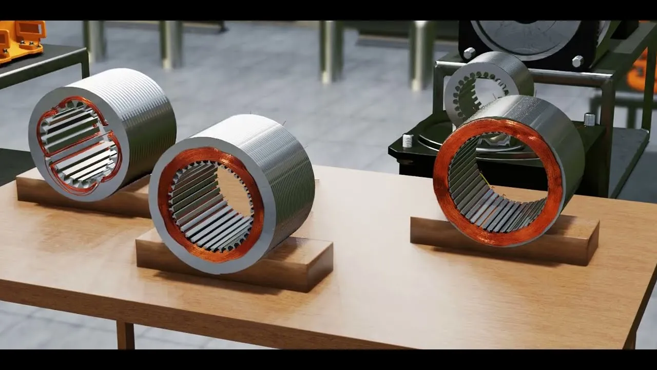
Motor winding refers to the coils of insulated wire that are wound around the core of a motor’s stator or rotor. These windings are responsible for generating the magnetic field needed to convert electrical energy into mechanical motion, a fundamental process in electric motor operation.
When an electric current passes through the motor winding, it creates an electromagnetic field. This field interacts with other magnetic components in the motor (such as permanent magnets or additional windings), producing torque and causing the rotor to spin. Without properly designed windings, the motor would be inefficient, unstable, or might not function at all.
There are two main types of motor windings based on their placement:
- Stator winding: Fixed windings mounted on the stationary part of the motor, responsible for creating a rotating magnetic field.
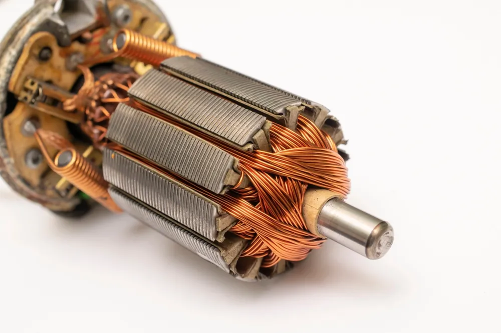
- Rotor winding: Windings located on the rotating part of the motor, found in certain motor types like wound rotor induction motors or synchronous motors.
In short, motor winding is the key component that brings the motor to life, transforming electrical power into precise, controlled movement.
Structure and Function of Motor Winding
Motor windings are carefully designed to optimize the conversion of electrical energy into mechanical motion. Their structure typically includes the following key components:
1. Core Components
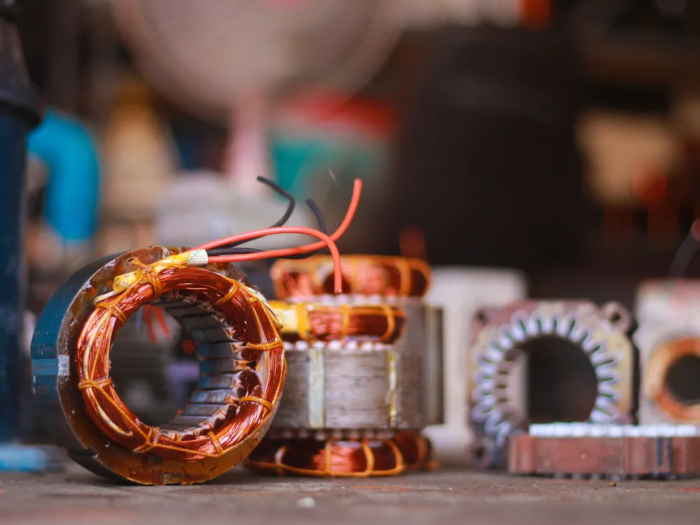
- Conductive wire: Usually made of copper (or sometimes aluminum), the wire is wound into coils. Copper is preferred for its excellent electrical conductivity and thermal stability.
- Insulation: Each winding is coated with a layer of insulation to prevent short circuits between adjacent coils or between the winding and the core.
- Winding slots: These are grooves in the stator or rotor core where the windings are placed, helping to hold the coils in position and optimize magnetic flux.
2. How It Works
When alternating current (AC) or direct current (DC) flows through the windings, it generates a magnetic field around the coil. This magnetic field interacts with the motor’s magnetic circuit, either from permanent magnets or opposing windings producing torque.
In AC motors:
- Stator winding receives the AC power.
- It creates a rotating magnetic field.
- This field induces current in the rotor, which begins to rotate due to the interaction of magnetic forces.
In DC motors:
- The winding is connected to a commutator, which switches the current direction to maintain rotational force.
3. Stator vs. Rotor Windings
- Stator windings are fixed and typically form the main magnetic field.
- Rotor windings are placed on the rotating shaft and respond to the stator’s magnetic field, creating motion.
A well-designed motor winding ensures:
- High energy efficiency
- Low thermal loss
- Stable torque output
- Longer motor lifespan
This makes winding structure not just a mechanical detail, but a crucial element in motor performance especially in high-precision applications like robotics, CNC machines, and linear motion systems.
Different Types of Motor Winding
Motor windings may appear simple at first glance just copper coils wrapped around a core but their design can dramatically affect the motor’s performance, efficiency, and application compatibility.
Engineers choose different winding types depending on voltage, current, motor size, desired torque output, heat dissipation, and cost. Below, we explore the main categories of motor winding based on construction, placement, phase, and coil distribution.
1. Classification by Construction Method
Lap Winding
Lap winding is a configuration where each coil end connects to the commutator segment adjacent to the next, forming multiple parallel paths for current flow.
- Where it’s used: Typically found in low-voltage, high-current DC machines, such as in electric locomotives or older industrial DC motors.
- Advantages:
- Higher current capacity due to multiple paths.
- Lower voltage per coil, safer for large machines.
- Limitations:
- Requires more conductor material.
- Slightly more complex to wind and balance.
Wave Winding
Wave winding connects coil ends to commutator segments that are spaced apart, so the current “waves” through the entire winding in series.
- Where it’s used: High-voltage, low-current applications, often seen in smaller or medium-sized DC machines.
- Advantages:
- Fewer parallel paths simplifies current control.
- Higher voltage per path.
- Limitations:
- Lower current handling.
- Less fault-tolerant than lap winding.
Frog-leg Winding (Hybrid)
A combination of lap and wave winding, frog-leg winding is used in special applications requiring compact construction with enhanced performance.
- Where it’s used: Large industrial DC motors or motors requiring customized performance characteristics.
- Advantages:
- Better space utilization.
- Balanced compromise between current and voltage needs.
2. Classification by Winding Location
Stator Winding
The stator winding is placed on the stationary part of the motor and is responsible for producing the main rotating magnetic field in AC machines.
- Where it’s used: All AC motors, including induction motors, synchronous motors, and linear motors.
- Design considerations:
- Must be well-insulated to prevent short circuits.
- Common shapes include distributed or concentrated configurations depending on the motor type.
- Material: Copper is standard, with insulation grades varying by application (thermal class B, F, H…).
Rotor Winding
Rotor windings are placed on the rotating part of the motor. Not all motors use them; squirrel-cage rotors rely on conductive bars instead.
- Where it’s used: Wound rotor induction motors and synchronous motors.
- Unique features:
- Often requires slip rings or brushes for external excitation or resistance control.
- More complex and costly to maintain.
3. Classification by Phase Configuration
Single-Phase Winding
A single-phase motor has only one alternating current supply, requiring additional components like a starting capacitor or auxiliary winding to initiate rotation.
- Where it’s used: Household appliances, fans, small pumps.
- Pros:
- Simple and cost-effective for light-duty use.
- Cons:
- Limited starting torque and efficiency.
- Not suitable for industrial-grade applications.
Three-Phase Winding
Three-phase windings use a three-phase AC power supply to create a rotating magnetic field naturally, eliminating the need for starting aids.
- Where it’s used: Industrial motors, automation systems, linear and servo motors.
- Pros:
- High efficiency and constant torque.
- Better load balancing and smoother operation.
- Cons:
- Requires three-phase power infrastructure.
4. Classification by Coil Arrangement
Concentrated Winding
In this design, coils are wound tightly around individual stator teeth. Each pole is formed by one or two concentrated coils.
- Where it’s used: Brushless DC motors (BLDC), stepper motors, and small servo motors.
- Advantages:
- High torque density and compact design.
- Easier to manufacture and automate.
- Drawbacks:
- Generates more cogging torque and harmonics.
- Less smooth rotation in high-precision systems.
Distributed Winding
Here, the coil turns are spread across multiple stator slots, forming a more sinusoidal magnetic field.
- Where it’s used: AC induction motors, synchronous motors, and high-end linear motors.
- Advantages:
- Smoother torque output and lower cogging.
- Better for continuous-duty, high-efficiency operations.
- Drawbacks:
- More complex winding process.
- Slightly lower torque density than concentrated types.
If you’re designing or selecting a motor for automation, robotics, or motion control, understanding these winding types is essential. ITG’s advanced motors, especially our high-performance linear motors, leverage optimized winding techniques to deliver industry-leading efficiency, responsiveness, and reliability.
Benefits of High-Quality Motor Winding
Behind every efficient and reliable motor lies a well-crafted winding system. Far from being just coils of copper, motor windings are the heart of electromagnetic motion and when engineered with precision, they unlock a wide range of performance advantages.
One of the most noticeable benefits of high-quality winding is energy efficiency. Well-designed windings minimize electrical resistance and reduce heat loss, allowing motors to deliver more power while consuming less electricity. In industries where machines run around the clock, even a small gain in efficiency can lead to significant cost savings over time.
Thermal performance is another critical factor. Motors often operate in high-load or high-speed environments, where poor winding design can cause rapid heat buildup. High-grade materials and tight winding tolerances help dissipate heat more effectively, reducing the risk of insulation breakdown or premature failure. This makes the motor not only safer but also more durable and maintenance-friendly.
Precision matters just as much. In motion control applications, especially in servo and linear motors the smoothness of the magnetic field directly impacts positioning accuracy. Quality winding ensures balanced magnetic flux, minimizing torque ripple, vibration, and cogging. The result is a motor that operates more quietly, more smoothly, and with better control even at high speeds or under complex load profiles.
Long-term reliability is perhaps the most underrated advantage. Motors with high-quality windings tend to have a longer service life, thanks to their resistance to mechanical wear, electrical stress, and environmental conditions. This translates to fewer shutdowns, lower repair costs, and greater peace of mind for engineers and operators alike.
Conclusion
Ultimately, the winding isn’t just a component, it’s a performance determinant. In demanding applications where precision, stability, and efficiency matter, choosing a motor with carefully engineered winding like those from ITG can make all the difference. Whether you’re building automation systems, robotics, or advanced manufacturing equipment, investing in quality winding is investing in consistent, high-value motion.